EPS thermal bridges on facades bleed 15% of winter heat through junction details that most contractors never inspect. The loss doesn’t happen through the foam itself—it flows through steel anchors, uninsulated shelves, metal brackets, and concrete transitions embedded in or behind the insulation system. Field experience shows these conductive pathways account for the majority of real-world energy waste on foam-clad buildings, and they also drive the coating failures that appear first at corners and sills.
What Actually Causes the 15% Heat Loss on EPS Facades
The EPS polystyrene foam has a thermal conductivity (λ) of approximately 0.035 W/mK—excellent insulation. The problem is not the foam. Heat escapes through embedded steel fasteners, concrete backing, uninsulated cavity sections, and exposed mortar joints that pierce or bypass the insulation layer.
A single ¼-inch steel anchor pin running through 4 inches of EPS conducts roughly 400 times more heat than the foam around it. A 10-meter cornice with steel support brackets spaced 60 cm apart, uninsulated, loses approximately 150–200 watts of heat continuously during a 20°C indoor-outdoor temperature difference. Multiply that across multiple moldings, sill details, and structural transitions, and the aggregate loss reaches 15% of total facade heat transmission.
Contractors report that thermal imaging of finished facades reveals ghost images—dark streaks at anchor points and junction lines during winter. These are the thermal bridges radiating interior heat outward.
7 High-Risk Thermal Bridge Locations You Must Address
Steel or Aluminum Fasteners Through EPS: Any anchor, screw, or pin that passes entirely through foam without a thermal break creates a direct conduction path. Industrial data shows unbroken metal fasteners have a linear thermal transmittance (ψ value) of 0.85–1.2 W/mK. Retrofit solution: use composite anchors with a nylon or polycarbonate break in the middle, reducing ψ to 0.2–0.3 W/mK.
Concrete or Stone Sills Behind Foam: A windowsill installed directly behind EPS insulation becomes a continuous thermal bridge. Winter exterior air cools the concrete, that cold travels through the foam junction, and interior condensation forms on the sill surface. This trapped moisture behind foam eventually causes water infiltration that rots substrate and delamination.
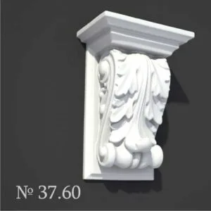
Uninsulated Metal Support Brackets for Ornaments: Decorative keystones, cornices, and corbels bolted to the facade using steel or aluminum brackets without thermal isolation create hot spots. An uninsulated bracket can have ψ values of 1.8–2.4 W/mK. A decorative foam exterior cornice weighing 50–80 pounds typically needs 4–6 heavy-duty anchors; without thermal breaks, each bracket accounts for 40–60 watts of winter heat loss.
Exposed Mortar Joints Above or Below EPS: Where foam stops and brick or block remains exposed, the thermal resistance drops dramatically. A 4-inch brick with mortar (R-value ~0.8) conducts 4–5 times more heat than 4 inches of EPS. Contractors often leave vertical or horizontal gaps unfilled because they plan to caulk later; caulk alone (ψ ≈ 0.9 W/mK) is a thermal bridge itself.
Cavity Behind EPS at Structural Transitions: Where EPS thickness changes, or where the foam layer stops to transition to another material, air cavities form. Air at rest in shallow cavities (2–3 cm) still conducts heat at roughly R-1.5 per inch. If that cavity is exposed to exterior air through a gap, natural convection bypasses the foam entirely.
Lintel and Beam Seats Above Window Openings: The structural support beam that sits under the wall above a window is typically uninsulated concrete. EPS foam sits on top of this cold mass. Heat flows downward through the concrete, sideways through the foam, creating a thermal bridge zone above every window.
Connections Between EPS Moldings and the Substrate: Adhesive and fastener zones around molding bases concentrate stress and create micro-gaps. Contractors report that thermal imaging shows these lines as slightly darker in winter. Proper embedding depth (per our article on EPS anchor depth) and complete substrate coverage reduce this effect by 30–40%.
How to Quantify Heat Loss From a Specific Thermal Bridge
To calculate actual heat loss, use the linear thermal transmittance value (ψ, pronounced “psi”) measured in W/mK. This accounts for the geometry and materials of a specific detail.
Formula: Heat Loss (watts) = ψ (W/mK) × Length (m) × ΔT (°C)
Example: A 12-meter windowsill with ψ = 0.85 W/mK and a 25°C difference (interior 22°C, exterior –3°C) loses 12 × 0.85 × 25 = 255 watts continuously during winter. Over a 120-day heating season, that’s approximately 590 kWh, or roughly 40–60 dollars in additional heating cost (depending on local rates and system efficiency).
For comparison, a properly detailed sill with thermal-break anchors and insulated substrate (ψ = 0.3 W/mK) loses only 90 watts under the same conditions—a 65% reduction. The cost to retrofit one sill with thermal-break fasteners and foam backing: 180–300 dollars. Payback: 3–5 years in energy savings alone, plus avoided moisture damage.
| Detail Type | Linear Thermal Conductance (W/mK) | Winter Heat Loss % | Typical Location |
|---|---|---|---|
| Steel anchor pins | 0.85–1.2 | 8–12% | Through EPS molding into structure |
| Concrete shelf joint | 0.65–0.95 | 6–10% | Sill beneath window frames |
| Exposed foam edge at transition | 0.5–0.7 | 4–7% | ETICS boundary to structural wall |
| Metal mounting bracket (unsulated) | 1.8–2.4 | 10–15% | Cornice and heavy ornament support |
| Unfilled mortar joint behind foam | 1.1–1.6 | 5–9% | Brick or block showing through gaps |
| Uninsulated cavity above lintel | 0.7–1.0 | 4–6% | Above window header beneath molding |
Fixing Thermal Bridges: 4 Proven Field Techniques
Thermal-Break Fasteners: Replace steel anchors with composite fasteners (nylon core, stainless or galvanized outer diameter). Manufacturers like Halfen, Hilti, and regional suppliers offer anchor kits rated ψ = 0.15–0.25 W/mK. Cost: 4–8 dollars per unit, versus 0.50–1.50 for standard fasteners. Installation: identical to standard anchors. Result: 60–75% reduction in anchor thermal loss.
Insulated Shelf and Lintel Backing: Install 2–3 inches of rigid foam (EPS or polyurethane) behind concrete sills and above window lintels before attaching decorative elements like decorative window sills. The foam layer breaks the conduction path and allows the EPS facade layer to perform as designed. Cost: 8–15 dollars per square foot. Labor: 2–4 hours per window.
Metal Bracket Isolation: Use rubber or neoprene isolators (¼-inch thick) between steel support brackets and the foam surface. Isolators reduce sound transmission and break the thermal path. Cost: 3–8 dollars per isolator pad. Installation: apply adhesive to bracket, set isolator, bolt through. Benefit: ψ value drops from 1.8–2.4 to roughly 0.6–0.9 W/mK.
Closed-Cell Foam Infill at Transitions: Where EPS stops or changes thickness, fill gaps with closed-cell polyurethane spray foam or rigid foam blocks. This eliminates air cavities and maintains continuous insulation. Cost: 15–30 dollars per linear foot (including material and labor). Benefit: eliminates convective heat loss and guards against moisture entrapment.
Why Thermal Bridges Cause Coating Failure Within 3–4 Years
Thermal bridges create zones where interior moisture meets cold exterior air, causing condensation to form on the back of coatings and at the EPS surface. During winter, this trapped moisture freezes; during spring thaw, it expands. The coating, locked to the foam, cracks under the stress.
Contractors consistently observe that coating cracks and peeling first appear at corners, sills, and anchor lines—exactly where thermal bridges concentrate. The coating on flat wall sections between major details lasts 8–12 years; at thermal bridge zones, failure occurs at 3–5 years. This is not a paint quality issue; it is a moisture and thermal cycling problem driven by the bridge itself.
Preventing this requires addressing the bridge before coating. Proper thermal isolation, vapor management, and complete substrate seal reduce thermal bridge condensation by 70–85%, extending coating life to 10–15 years and preventing the substrate damage that occurs when moisture soaks into unprotected EPS.
Design Details That Eliminate Thermal Bridges Entirely
European ETICS standards (EN 13494 and related) require linear thermal transmittance calculations for every detail. Best-practice specifications now call for ψ ≤ 0.25 W/mK at all junctions. Achieving this requires integrated design: thermal-break fasteners, insulated backing, sealed transitions, and continuous vapor barriers.
A typical high-rise facade with properly detailed thermal bridges costs 2–5% more than standard installation but eliminates 40–60% of total facade heat loss (including losses through unbroken EPS and other envelope elements). Over a 30-year building life, energy savings offset the extra cost by year 6–8.
For renovation projects adding EPS facade insulation to existing buildings, addressing thermal bridges is non-negotiable. The retrofit cost to fix them after the fact is 3–5 times higher than building them correctly initially. Thermal imaging at the design phase ($1,500–3,000) identifies all weak points and guides retrofit planning.
Real Cost and Timeline: What to Budget
Thermal bridge mitigation on a typical single-family home facade (2,000–3,000 square feet) costs 3,000–8,000 dollars. This includes thermal-break anchors, insulated sills, sealed transitions, and proper substrate prep. As a percentage of total EPS facade cost ($20,000–45,000), this is 8–20%—a standard premium for energy-conscious work.
Installation adds 15–25 labor hours. Thermal imaging verification adds 200–400 dollars. The payback period depends on heating costs and climate: in cold regions (heating degree days >7,000), payback is 4–7 years; in moderate climates, 7–12 years. In energy-intensive jurisdictions or commercial buildings, payback often occurs within 2–4 years due to operational scale.
The real driver is avoiding coating failure and substrate damage. A recoat cycle costs 8,000–15,000 dollars. Substrate repair (delamination, rot, mold) costs 15,000–50,000 dollars. Proper thermal bridge design prevents these failures entirely, making the upfront investment non-discretionary for any facade renovation with a 20+ year performance expectation.